Figure 1 from Design considerations and approaches for sensor interface Circuit Diagram
Figure 1 from Design considerations and approaches for sensor interface Circuit Diagram Typically, the bandwidth for temperature sensors is much lower than 50 or 60 Hz so a simple low-pass filter will work well in many cases. Other measures to keep noise away: • Keep the sensor wires short. • Use shielded sensor cables with twisted pair wires. • Use a dedicated precision voltage reference, not the microcontroller supply.

In my case, I have a fair amount of experience with sensors and Microchip PIC microcontrollers, Arduino-compatible boards, and Raspberry Pi variants. With a protocol-based interface, the sensor and MCU communicate by sending a data stream. In fact, most protocol-based sensors have their own tiny MCU built into the chip or located inside the

Understanding Sensor Interfaces Circuit Diagram
I've been learning to program 32-bit ARM cortex-M controllers with an STM32 Nucleo (L476rg Nucleo). I've been playing with interfacing and controlling stepper motors so far. My next step is to move on to machine/computer vision and incorporate image sensing however upon some searching (hopefully
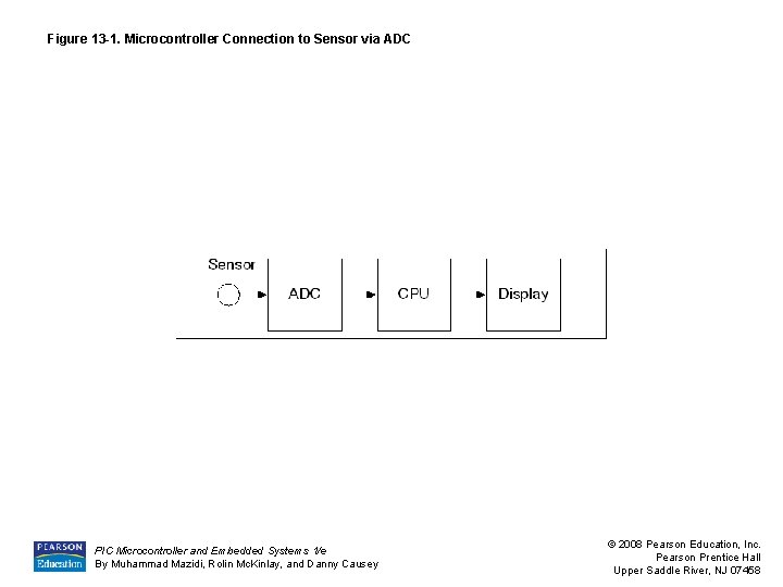
This article discusses the "ins and outs" of interfacing analog sensors to a microcontroller's analog-to-digital converter (ADC) input pins 1.As shown later in Table 1, a great number of sensors produce a voltage output that varies in response to a change in a physical parameter such as temperature, pressure, or magnetic field intensity.. Voltage output sensors with low output impedance

PDF Microcontroller to Sensor Interfacing Techniques Circuit Diagram
The microcontroller communicates with the sensors and actuators to acquire data or trigger actions based on the input received. The interfacing process involves the following steps: Identify the Sensor or Actuator: Determine the type and specifications of the sensor or actuator you want to interface with. Common examples include temperature Once selected, these devices need to be connected to the microcontroller using various interface protocols like I2C or SPI. Proper wiring techniques ensure reliable communication between the microcontroller and peripherals. Ensure all connections between the microcontroller, sensors, and actuators are secure. Verify that the correct pins In simple terms, sensor interfacing is the process of connecting sensors to microcontrollers or other processing systems. This allows microcontrollers to acquire, process, and respond to sensor data, facilitating real-time environmental interaction. This interface enables microcontrollers to: Acquire the signals from sensors

Select the Appropriate Microcontroller and Sensors. Evaluate the sensor requirements, such as type (e.g., temperature, pressure), communication protocol (e.g., I2C, SPI, UART), and voltage levels. Choose a microcontroller that supports the necessary communication interfaces and has sufficient processing power for the application.
