hall effect speedometer for bike Circuit Diagram
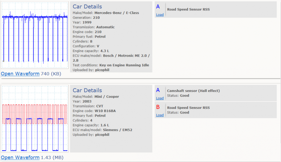
hall effect speedometer for bike Circuit Diagram Hello, hope you are well. I have a project in electronics in which I need to measure the rotational speed of a fan using a hall effect sensor and display this speed on a 16x2 lcd. I have no problem with the display on the LCD. But I don't know how to go about it with the hall effect sensor to be able to measure the rotational speed of a fan. Hello, I am trying to measure the speed of a bicycle wheel using a hall effect sensor. I am using the code below and get the RPM which I then convert into m/s. However, I want the measurement to be more accurate. Using my code the RPM changes by 60 which is roughly 2 m/s. I want a more accurate speed measurements with not such big intervals

I'm using an ominpolar hall effect sensor from Allegro I think, I've used these in the past for another project and it seems to be working fine. It's reading the magnet, and I've done the basic sketch to illuminate the on board LED of the UNO. The screen is a basic 128 x 32 OLED thing, and again it's functioning well.

How to use Hall Effect Sensor with Arduino? Circuit Diagram
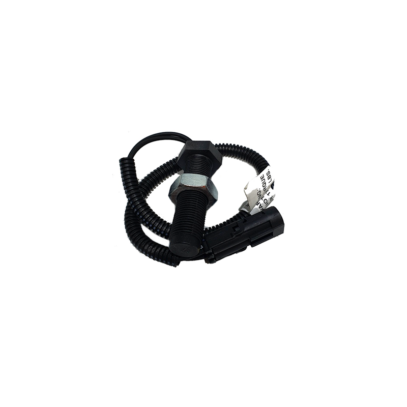
However, for applications that involve high-speed detection, like in the case of speedometers, high-frequency Hall Effect sensors like US5881 or US1881 should be used. There are two main types of Hall Effect sensors: Latching Hall Effect sensors. Non-latching Hall Effect sensors. The US1881 is a latching Hall Effect sensor.
Use a Hall effect sensor to detect the presence of a magnet and make a speedometer, a burglar alarm, and more! For applications where the speed of detection is not crucial, ordinary Hall effect sensors like 44E can be used. However, for applications that involve high-speed detection, like in the case of speedometers, high-frequency Hall
A Simple Guide to Using a Hall Effect Sensor With Arduino Circuit Diagram
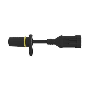
A hall effect sensor can detect the presence of a magnetic field and is often used for positioning objects or measuring rotation. For example you could use one to measure the speed of a bike wheel by attaching a magnet to one of the spokes. In order to test the idea and check the distance at which the sensor would trigger I decided to use a
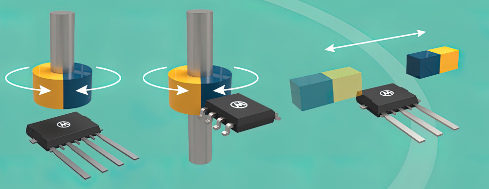
A Hall-effect sensor varies its output voltage in response to a magnetic field. Hall-effect devices are used as proximity sensors and for positioning, speed, and current detection. They are widely used in motor control systems. A Hall-effect sensor is a long-lasting solution because there are no mechanical parts to wear down over time.