Lab Circuit Diagram
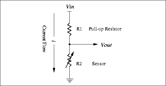
Lab Circuit Diagram Key learnings: Voltage Divider Definition: A voltage divider is a simple circuit that creates a part of its input voltage as output, using two resistors in series.; Circuit Components: The circuit includes two resistors connected in series with a voltage source, splitting the input voltage.; Unloaded Equation: With no current flowing out, the output voltage depends on the ratio of the resistors.

A voltage divider is a circuit that creates a smaller voltage from an input voltage by using two resistors. You'll see it in both simple and advanced circuits all the time. Here's the basic setup: For example, the thermistor is a temperature sensor. It changes its resistance based on the temperature. This is where the hero: A voltage divider comes in and saves the day acting as a level shifter which interfaces two circuits that use different operating voltages. The voltage divider can help level the voltage down from a microcontroller (eg. 5V to 3.3V) to avoid damage to the sensor which makes it safe for the sensor to handle. A voltage divider is a simple circuit which turns a large voltage into a smaller one. Using just two series resistors and an input voltage, we can create an output voltage that is a fraction of the input. Real-life voltage divider applications. Suggested Reading. This tutorial builds on basic electronics knowledge. If you haven't already
Circuits, Equation and Applications Circuit Diagram
Figure 2: Resistive Voltage Divider Circuit. The input voltage V in is applied across the two resistors R 1 & R 2 which are connected in series. The output voltage V out is obtained between the two terminals of the resistor R 2. The voltage across this resistor will be a fraction of the input voltage V in. The formula to calculate the output of

In this video, I am talking about what is a voltage divider, how it works, and how to use it as a voltage sensor.Join this channel to support me or to get ac Voltage Divider Circuits are very important in Analog Electronics as well as Sensor interfacing to the microcontrollers. Basic operation of this simple circuit is to reduce the input Voltage level (Vin) into desired Low Voltage Output (Vout) by using two passive Resistors. By understanding its operation and needs we can bias any components with the given input voltage. A voltage divider is a simple yet powerful circuit that reduces a higher voltage to a lower one using two resistors. It is commonly used to reduce the voltage for devices that require lower operating voltages, such as sensors or microcontrollers. The output voltage of a voltage divider can be calculated using the voltage divider equation: Where:
