Water level monitoring simplest way Circuit Diagram
Water level monitoring simplest way Circuit Diagram A water level sensor detects the presence or level of water by measuring changes in conductivity. It typically consists of a set of exposed conductive traces that act as probes. When water bridges the gaps between the traces, the sensor produces an electrical signal indicating water presence or level.

The float sensor is a device used to detect the level of liquid within a tank. The magnet inside the bulb structure is an electromagnetic ON/OFF switch that helps to sense the level of water present in the overhead tank or sump. You can use any type of float sensor switch such as a reed float switch or anything else.

Arduino UNO Based Water Level Indicator with Alert System Circuit Diagram
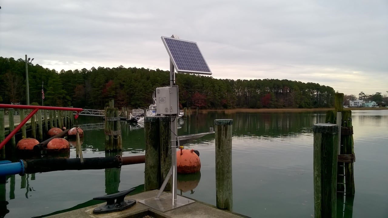
You can see your water sensor information on maps, graphs, tables, and configure custom alerts for when the water levels go too high or low. You can also use web dashboards to quickly see what's going on in the field with multiple water level systems with IoT sensors. More photos and further info on flood monitoring systems is available for you
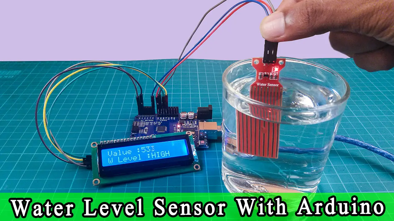
Water Level Sensor. A device that detects the level of water in an environment; It has a signal output (SIG) which varies depending on the water level, a power supply pin (VCC), and a ground pin (GND). LED: Two Pin (yellow) A yellow light-emitting diode with an anode and cathode for indicating statuses or alerts. LED: Two Pin (green) Data Transmission: Once the water level data is processed, the ESP32 uses its Wi-Fi capability to connect to the internet. It sends the water level information to a central server or a cloud platform. Cloud Server: The central server or cloud platform collects and stores the incoming data. This server can be accessed remotely for real-time

Water Level Sensor with Arduino Tutorial Circuit Diagram
Overview. This article explores a water level alert circuit using a 555 timer and a float sensor, designed to detect and signal when water reaches a predefined level. The NE555 timer IC is a versatile and cost-effective solution for creating automated alert systems.This project is ideal for applications like water tanks, reservoirs, or flood detection systems.

For a more detailed explanation of the water level sensor, check out this article: How to Use a Water Level Sensor with Arduino: A Step-by-Step Guide Why Monitor Water Levels? Water level monitoring is essential for various applications: Smart Water Tanks: Prevent overflows or running dry. Hydroponics: Keep water at optimal levels for plant health.
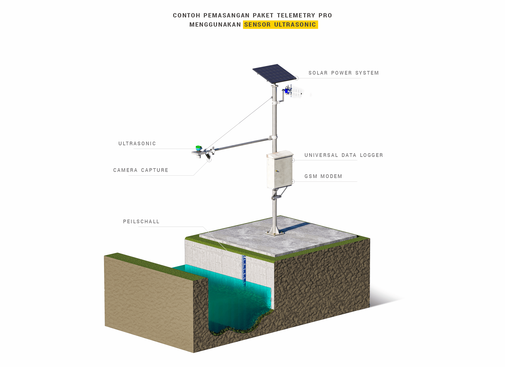
GSM Based Water Level Monitoring System with Arduino Circuit Diagram
Explore comprehensive documentation for the Arduino-Based Flood Warning System with GSM Alert and Audio Warning project, including components, wiring, and code. This project is an Arduino UNO-powered flood warning system that utilizes multiple water level sensors to monitor water levels in real-time. When water levels exceed a predefined threshold, the system sends out SMS alerts via a SIM800L